
-
 Email: admin@ytoptics.com
-
 English Inquiry Support:
-
 Add: 2# Automotive InnovationPark,
City,Jilin Province, China
Selection Logic of Optical Components in High‑Power Laser Systems: Three Key Loss Parameters Beyond
In laser system integration, the selection of optical components often begins with nominal parameters such as reflectance and transmittance; however, for high-power continuous-wave lasers or low-gain resonator systems, making decisions based solely on these parameters may pose potential risks. From an engineering perspective, this article analyzes the actual impact of absorption loss, scattering loss, and surface profile deviations on laser system performance, and explains Yutai Optics’ approach to quality control in the processing and inspection of optical components.
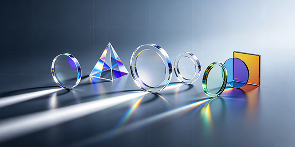
The nominal reflectivity of laser cavity mirrors is typically specified as “≥99.9%” or “≥99.99%,” but this value represents the theoretical upper limit of specular reflection under ideal conditions. In an actual resonant cavity, photons travel back and forth dozens or even hundreds of times, and the minute additional loss incurred on each single-pass cycle is amplified exponentially.
Let the reflectivities of the two mirrors be R₁ and R₂, respectively, and the additional loss per round trip be δᵢ. Then, the surviving power after n round trips is:
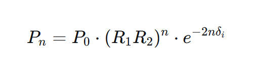
Therefore, total loss is the core parameter in resonator design, while reflectance is merely one of its components.
II. Three Underestimated Loss Parameters
1. Absorption Loss: The Root Cause of Thermal Effects
Absorption loss refers to the proportion of a photon’s energy that is absorbed by a coating or substrate and converted into lattice heat. For high-power 1064 nm laser systems, even if the absorption loss is only on the order of 100 ppm, the focal shift of a 300 mm focusing lens can reach tens of millimeters at a continuous power of 6 kW. Focal shift directly causes the processing focus to drift, affecting process stability in applications such as welding and cutting.
Engineering Implications: In high-power continuous-wave laser systems, absorption loss should be the primary criterion for lens selection.
2. Scattering Loss: A Source of Parasitic Oscillations and Noise
Scattering loss does not directly heat the lens, but scattered light may couple back into the gain medium, causing parasitic oscillations, or be reflected off the cavity walls and re-enter the optical path, introducing intensity noise. In high-gain lasers, scattering feedback may even induce self-locking modes or alter the relaxation oscillation frequency.
Engineering Implications: In ultrashort-pulse lasers and high-gain systems, controlling scattering loss is more critical than controlling absorption loss.
3. Surface Profile Deviation: Accumulation of Wavefront Distortion
The surface profile accuracy of a lens (e.g., λ/10, λ/4) directly affects the phase distribution of the reflected wavefront. In multi-mirror cavities, surface profile deviations accumulate step by step, leading to a deterioration of the output beam’s M² factor. For applications requiring long-distance transmission or precision focusing, surface flatness is often a more critical concern than reflectivity.
Engineering Implications: In multi-mirror resonant cavities and precision focusing systems, priority should be given to ensuring surface flatness specifications.
III. Loss Decomposition: From “Total Loss” to “Loss Components”
Two optical elements with the same total loss may have completely different failure modes. The table below shows typical loss decomposition data for a 1064 nm highly reflective mirror (illustrative):
|
Sample |
Nominal Reflectance |
Total Losses/ppm |
Scattering Loss/ppm |
Absorption Loss/ppm |
Dominant Mechanism |
| M1 |
99.99% |
120 | 45 | 75 |
Absorption-Scattering Equilibrium |
| M2 |
99.99% |
118 | 12 | 106 |
Absorption-led |
| M3 |
99.95% |
620 | 380 | 240 |
Scattering-dominated |
Although M2 and M1 have the same nominal values, their loss compositions differ significantly: M2 has scattering loss as low as 12 ppm, indicating excellent control of the film interface roughness; however, its absorption loss is as high as 106 ppm, suggesting insufficient film density. Under continuous high-power operating conditions, the thermal performance of M2 will be significantly inferior to that of M1.
This is precisely where the value of separated loss measurement lies: it elevates the selection process from simply “looking at the total loss figure” to “assessing whether the loss composition matches the application scenario.”
IV. Our Company’s Quality Control Approach
Based on the above analysis, our company has established the following control processes for the machining and inspection of optical components:
Substrate Selection: Based on the application’s power density and wavelength, we select suitable substrate materials (fused quartz, BK7, CaF₂, etc.) to control substrate absorption and the coefficient of thermal expansion.
Coating Process Control: For high-power applications, we employ a dense coating process to reduce absorption loss; for ultrashort-pulse applications, we optimize interface roughness to suppress scattering.
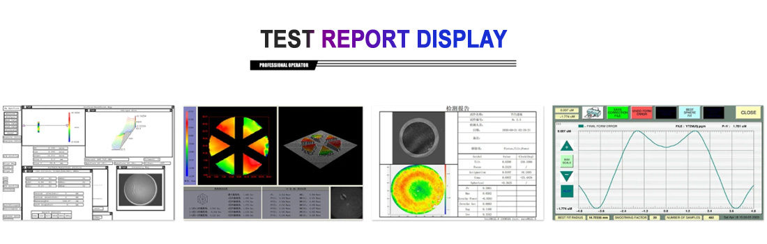
Factory Testing: Equipped with a cavity ring-down (CRD) loss measurement system, an integrating sphere scattering measurement device, and an interferometer for surface profile inspection, we perform loss separation testing on products such as high-reflectivity mirrors and filters to ensure that factory specifications align with actual application scenarios.
Application Matching Recommendations: We provide tailored component selection recommendations based on the power level, gain characteristics, and pulse width of the customer’s laser system.
V. Quick Reference Guide for Model Selection
|
Application Scenarios |
Primary Considerations |
Secondary Considerations |
|
High-power continuous-wave lasers (>1 kW) |
Absorption loss |
Spot size accuracy |
|
Low-gain resonators (e.g., Yb:YAG) |
Total Loss |
Scattering Loss |
|
Ultrashort-Pulse Lasers (fs/ps) |
Scattering Loss |
Spot Shape Accuracy |
|
Precision Focusing/Long-Distance Transmission |
Spot Shape Accuracy |
Total Loss |
|
High-Gain Lasers |
Scattering Loss |
Absorption Loss |


NEXT : What is the difference between concave and convex optical lenses?
 86-15584132290
Call us now!

 2433808388