ISO9001 Certified Professional Manufacturer & Supplier of Optics
+86-0431-87911611 admin@ytoptics.com

Contact us
-
 Email: admin@ytoptics.com
-
 English Inquiry Support:
-
 Add: 2# Automotive InnovationPark,
City,Jilin Province, China
Engineering Considerations for Optical Window Parallelism
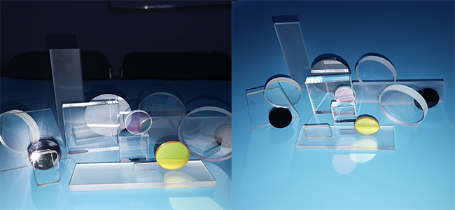
Windows are typically intended solely for protective purposes and do not participate in optical power distribution, so engineers often pay insufficient attention to them during the design phase. However, the seemingly simple geometric specification of window parallelism gives rise to far more complex system-level issues in practical engineering than one might expect—ranging from beam deviation causing optical axis misalignment, to transmitted wavefront distortion degrading imaging quality, and even to yield loss due to difficulties in ensuring coating uniformity—all of which are directly related to parallelism.
1. Parallelism and Wedge Angle
Ideally, an optical window should have two surfaces that are strictly parallel to each other. In actual manufacturing, however, there is invariably a small angle between the two surfaces, known as the wedge angle. Parallelism and wedge angle are two sides of the same coin—the smaller the wedge angle, the higher the degree of parallelism.
Common industry specifications:
2.System-Level Effects of Parallelism Deviation
(1) Beam Deviation
A beam passing through a wedged window undergoes angular deviation, given by δ ≈ (n−1)·α. Taking N-BK7 (n ≈ 1.517) as an example, a 1° wedge angle produces a deviation of approximately 0.52°. In a long optical path system, this deviation alone is sufficient to shift the spot off the detector's active area by several millimeters.
(2) Transmitted Wavefront Distortion
Non-parallel surfaces of a window effectively act as an extremely thin wedge prism. The optical path difference (OPD) across the clear aperture D is ΔOPD ≈ (n−1)·α·D. When this exceeds λ/4, it becomes non-negligible and directly degrades the accuracy of interferometric measurements.
(3) Cascading Effects on Adjacent Optics
Windows are often placed in front of filters and lenses. Their wedge angle alters the beam incidence angle onto subsequent optical elements, causing spectral shifts in filters. In multi-element systems, individual deviations accumulate and amplify, necessitating systematic error budget allocation at the system level.
(4) Constraints on Coating Processes
Wedge angle causes variations in distance and orientation relative to the evaporation source across different regions of the window surface. For products sensitive to coating thickness uniformity—such as multi-cavity filters—substrate wedge deviation directly translates into reduced production yield.
3. Manufacturing Constraints on Parallelism
The difficulty of fabrication varies significantly across materials: fused silica, with its low coefficient of thermal expansion and moderate hardness, is the easiest to control; infrared materials such as silicon, being hard or brittle, present greater difficulty; crystalline materials like calcium fluoride, which have cleavage planes, are the most challenging as machining stress can readily induce cracking.
Controlling parallelism for large-aperture windows is considerably more difficult than for small-aperture ones—factors such as equipment precision, lap uniformity, and fixturing stress all scale with aperture size. When the aperture exceeds 100 mm, maintaining stable control within 1′ already poses a significant engineering challenge.
4. Parallelism Inspection
5. Selection Guidelines
Parallelism and surface figure accuracy have a superimposed effect on transmitted wavefront quality. When the system has explicit requirements for transmitted wavefront, both specifications should be consolidated and allocated within a unified error budget. In multi-window cascaded systems, the deviations of individual elements accumulate according to optical propagation relationships, necessitating the establishment of an error budget table for rational allocation.
The parallelism of an optical window is tied to multiple factors, including wavefront quality, manufacturability, and coating yield. When specifying and selecting windows, engineers should strike a rational balance among performance, cost, and manufacturability.
1. Parallelism and Wedge Angle
Ideally, an optical window should have two surfaces that are strictly parallel to each other. In actual manufacturing, however, there is invariably a small angle between the two surfaces, known as the wedge angle. Parallelism and wedge angle are two sides of the same coin—the smaller the wedge angle, the higher the degree of parallelism.
Common industry specifications:
|
Grade |
Parallelism |
Typical Applications |
|
High Precision |
<1″ |
Laser interferometers, precision metrology |
|
Precision |
1″–1′ |
High-resolution imaging, spectrometers |
|
Industrial |
1′–3′ |
General optical systems, protective windows |
|
Coarse |
3′–10′ |
Illumination systems, non-imaging applications |
2.System-Level Effects of Parallelism Deviation
(1) Beam Deviation
A beam passing through a wedged window undergoes angular deviation, given by δ ≈ (n−1)·α. Taking N-BK7 (n ≈ 1.517) as an example, a 1° wedge angle produces a deviation of approximately 0.52°. In a long optical path system, this deviation alone is sufficient to shift the spot off the detector's active area by several millimeters.
(2) Transmitted Wavefront Distortion
Non-parallel surfaces of a window effectively act as an extremely thin wedge prism. The optical path difference (OPD) across the clear aperture D is ΔOPD ≈ (n−1)·α·D. When this exceeds λ/4, it becomes non-negligible and directly degrades the accuracy of interferometric measurements.
(3) Cascading Effects on Adjacent Optics
Windows are often placed in front of filters and lenses. Their wedge angle alters the beam incidence angle onto subsequent optical elements, causing spectral shifts in filters. In multi-element systems, individual deviations accumulate and amplify, necessitating systematic error budget allocation at the system level.
(4) Constraints on Coating Processes
Wedge angle causes variations in distance and orientation relative to the evaporation source across different regions of the window surface. For products sensitive to coating thickness uniformity—such as multi-cavity filters—substrate wedge deviation directly translates into reduced production yield.
3. Manufacturing Constraints on Parallelism
The difficulty of fabrication varies significantly across materials: fused silica, with its low coefficient of thermal expansion and moderate hardness, is the easiest to control; infrared materials such as silicon, being hard or brittle, present greater difficulty; crystalline materials like calcium fluoride, which have cleavage planes, are the most challenging as machining stress can readily induce cracking.
Controlling parallelism for large-aperture windows is considerably more difficult than for small-aperture ones—factors such as equipment precision, lap uniformity, and fixturing stress all scale with aperture size. When the aperture exceeds 100 mm, maintaining stable control within 1′ already poses a significant engineering challenge.
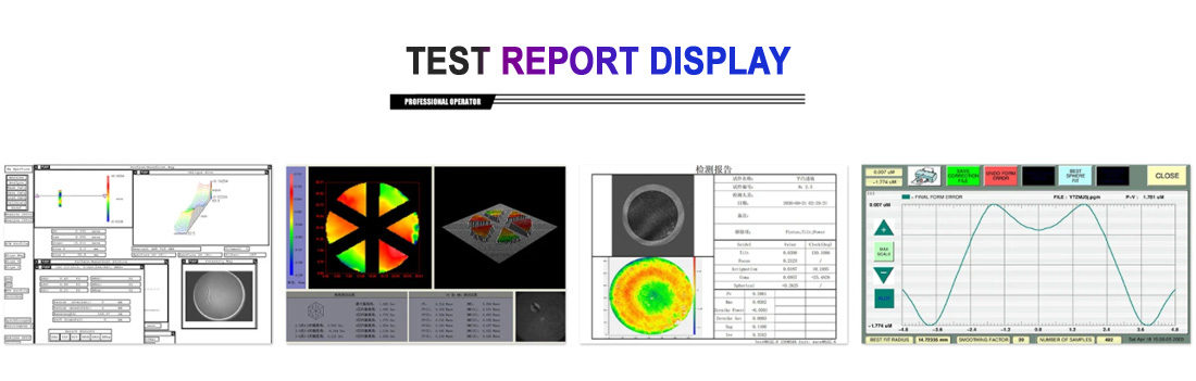
4. Parallelism Inspection
|
Method |
Accuracy |
Applicable Scenarios |
|
Autocollimator Method |
±2″–±5″ |
Production line batch sampling inspection; low equipment cost |
|
Interferometric Method |
≤0.5″ |
Final inspection of precision components; highest accuracy |
|
CMM / Coordinate Measuring Method |
Micrometer-level |
Large-size components; low efficiency |
5. Selection Guidelines
|
Application Scenario |
Recommended Parallelism |
Remarks |
|
Laser interferometers, precision metrology |
≤1″ |
Accompanied by interferometric test report |
|
High-resolution imaging, spectrometers |
1″–1′ |
Evaluate together with surface figure specifications |
|
General optical systems |
1′–3′ |
Balance cost and performance |
|
Protective windows, illumination systems |
3′–10′ |
Excess precision offers no added value |
|
Laser output windows |
0.5°–3°wedge angle |
Intentional wedge introduced to eliminate etalon effects |
Parallelism and surface figure accuracy have a superimposed effect on transmitted wavefront quality. When the system has explicit requirements for transmitted wavefront, both specifications should be consolidated and allocated within a unified error budget. In multi-window cascaded systems, the deviations of individual elements accumulate according to optical propagation relationships, necessitating the establishment of an error budget table for rational allocation.
The parallelism of an optical window is tied to multiple factors, including wavefront quality, manufacturability, and coating yield. When specifying and selecting windows, engineers should strike a rational balance among performance, cost, and manufacturability.
Share this:


PREV : From Rough Grinding to Coating: A Technical Breakdown of the Optical Component Manufacturing Process NEXT : Exposing the Flange Edge: A Novel Optical Dome Clamping Method to Overcome Machining Dimension Devia
TALK TO US 86-15584132290
Call us now!
86-15584132290Call us now!

ONLINE CHAT
 2433808388
2433808388