ISO9001 Certified Professional Manufacturer & Supplier of Optics
+86-0431-87911611 admin@ytoptics.com

Contact us
-
 Email: admin@ytoptics.com
-
 English Inquiry Support:
-
 Add: 2# Automotive InnovationPark,
City,Jilin Province, China
How to Ensure Focal Line Uniformity of a Cylindrical Lens in a Laser Line Scanning System?
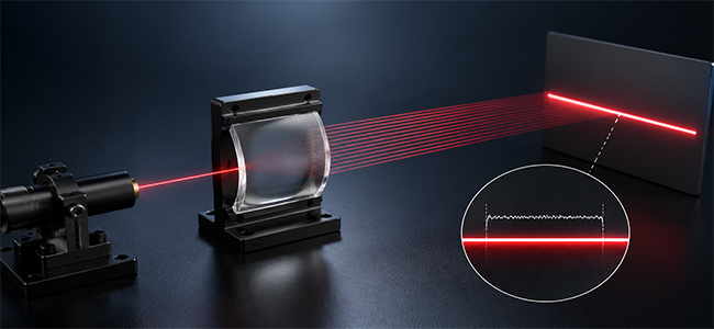
In laser line-scan systems (3D profile measurement, line laser displacement sensors, and laser marking), the key performance indicator is the energy uniformity along the laser line. An uneven focal line directly results in:
3D measurement: Inconsistent reflection signal intensity at different positions at the same height, resulting in increased measurement data dispersion;
Laser marking: Overburning in high-energy areas of the focal line and unclear marking in low-energy areas.
However, the focal line produced by a cylindrical lens inherently suffers from non-uniform energy distribution.
1. Three Determining Factors
1.1 Factor 1: The Transverse Mode of the Incident Beam
The energy distribution along the focal line of a cylindrical lens is essentially a “stretching” of the intensity distribution of the incident light in the focal direction along the focal line. If the incident light is a Gaussian beam in the fundamental transverse mode (TEM00), the energy distribution along the focal line is Gaussian—strongest at the center and gradually weakening toward the ends—and its non-uniformity is determined by the ratio of the full width at half maximum (FWHM) of the Gaussian curve to the effective length of the focal line.
In engineering practice, this can be improved using top-hat shaping techniques: inserting a top-hat beam shaper (such as a compound lens or DOE) in front of the cylindrical lens converts the Gaussian distribution into a top-hat distribution. However, this increases system cost and insertion loss, requiring a trade-off assessment of whether it is worthwhile.
A more economical approach is to control the utilization rate—by using the central portion of the Gaussian distribution (the length corresponding to approximately 80% of the energy) as the effective focal line length, while discarding the “tails” at both ends where the energy is lower. This strategy does not require additional components but sacrifices the utilization rate of the incident light.
Energy distribution trends of the focal lines for the two types of spots (qualitative):
1.2 Factor 2: Cylindrical Lens Surface Accuracy
Cylindrical lens surface errors (primarily errors in generatrix straightness and PV errors in the curvature surface) introduce phase modulation along the focal line, manifesting as local fluctuations in energy along the focal line—that is, alternating light and dark stripes appear on what should otherwise be a smooth focal line.
The quantitative relationship between generatrix straightness errors and the non-uniformity of light intensity along the focal line can be expressed as: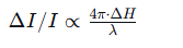 Where ΔH represents the straightness deviation of the generatrix (PV value). When ΔH reaches λ/10, the theoretical light intensity is approximately ±12%.
Engineering Recommendations:
Conventional laser scanning system: Surface accuracy requirement λ/4@633nm, corresponding to a generatrix straightness better than 0.15μm;
High-precision measurement system: Surface accuracy requirement λ/10@633nm, generatrix straightness better than 0.06μm.
1.3 Factor 3: Single Cylindrical Lens vs Dual Cylindrical Lens Combination
A single cylindrical lens performs direct focusing, where the energy distribution along the focal line fully inherits the characteristics of the incident beam (Gaussian or flat-top profile), leaving limited engineering means for active control.
A typical configuration of a dual cylindrical lens combination consists of a cylindrical beam expander followed by a cylindrical focusing lens. The principle for improving focal line uniformity is as follows: the first cylindrical lens (beam expander) expands the beam in the focusing direction, effectively "broadening" the intensity distribution of the beam spot along the focusing direction; the second cylindrical lens (focusing lens) then focuses this broadened beam into a focal line. With a flatter intensity distribution across the focusing direction and a relatively small incident beam divergence angle, the intensity fluctuations along the focal line are effectively smoothed out.
However, it should be noted that the cylindrical beam expander alters the beam spot size, which in turn affects the minimum line width of the focal line. The focal lengths of the two cylindrical lenses must be matched through careful design: a larger expansion ratio yields better focal line uniformity but inevitably leads to a corresponding increase in the minimum line width.
2. Summary of Engineering Control Methods
3. Experimental Results
4. Selection Recommendations
Remarks on the Front‑End Flat‑Top Shaping Scheme:
If a DOE or fly‑eye lens array is added solely for the purpose of improving uniformity, the following factors must be carefully considered:
① Whether the insertion loss introduced by the additional optical components is acceptable;
② The M² factor of a flat‑top beam is generally larger than that of the original Gaussian beam, which leads to an increase in the diffraction‑limited line width;
③ The overall system cost increases significantly.
For the vast majority of engineering applications, the dual cylindrical lens combination represents the most cost‑effective and well‑balanced solution.
3D measurement: Inconsistent reflection signal intensity at different positions at the same height, resulting in increased measurement data dispersion;
Laser marking: Overburning in high-energy areas of the focal line and unclear marking in low-energy areas.
However, the focal line produced by a cylindrical lens inherently suffers from non-uniform energy distribution.
1. Three Determining Factors
1.1 Factor 1: The Transverse Mode of the Incident Beam
The energy distribution along the focal line of a cylindrical lens is essentially a “stretching” of the intensity distribution of the incident light in the focal direction along the focal line. If the incident light is a Gaussian beam in the fundamental transverse mode (TEM00), the energy distribution along the focal line is Gaussian—strongest at the center and gradually weakening toward the ends—and its non-uniformity is determined by the ratio of the full width at half maximum (FWHM) of the Gaussian curve to the effective length of the focal line.
In engineering practice, this can be improved using top-hat shaping techniques: inserting a top-hat beam shaper (such as a compound lens or DOE) in front of the cylindrical lens converts the Gaussian distribution into a top-hat distribution. However, this increases system cost and insertion loss, requiring a trade-off assessment of whether it is worthwhile.
A more economical approach is to control the utilization rate—by using the central portion of the Gaussian distribution (the length corresponding to approximately 80% of the energy) as the effective focal line length, while discarding the “tails” at both ends where the energy is lower. This strategy does not require additional components but sacrifices the utilization rate of the incident light.
Energy distribution trends of the focal lines for the two types of spots (qualitative):
|
Incident Light Spot Type |
Energy Distribution Trend Along the Focal Line |
Non-uniformity Within the Effective Focal Line |
|
Gaussian Beam (TEM00) |
High in the center, gradually decreasing at both ends, forming a Gaussian shape |
Approximately 12%–18% |
|
Top-Hatted Beam |
Flat in the center, with steep drops at both ends |
Approximately 3%–5% |
1.2 Factor 2: Cylindrical Lens Surface Accuracy
Cylindrical lens surface errors (primarily errors in generatrix straightness and PV errors in the curvature surface) introduce phase modulation along the focal line, manifesting as local fluctuations in energy along the focal line—that is, alternating light and dark stripes appear on what should otherwise be a smooth focal line.
The quantitative relationship between generatrix straightness errors and the non-uniformity of light intensity along the focal line can be expressed as:
Where ΔH represents the straightness deviation of the generatrix (PV value). When ΔH reaches λ/10, the theoretical light intensity is approximately ±12%.Engineering Recommendations:
Conventional laser scanning system: Surface accuracy requirement λ/4@633nm, corresponding to a generatrix straightness better than 0.15μm;
High-precision measurement system: Surface accuracy requirement λ/10@633nm, generatrix straightness better than 0.06μm.
1.3 Factor 3: Single Cylindrical Lens vs Dual Cylindrical Lens Combination
A single cylindrical lens performs direct focusing, where the energy distribution along the focal line fully inherits the characteristics of the incident beam (Gaussian or flat-top profile), leaving limited engineering means for active control.
A typical configuration of a dual cylindrical lens combination consists of a cylindrical beam expander followed by a cylindrical focusing lens. The principle for improving focal line uniformity is as follows: the first cylindrical lens (beam expander) expands the beam in the focusing direction, effectively "broadening" the intensity distribution of the beam spot along the focusing direction; the second cylindrical lens (focusing lens) then focuses this broadened beam into a focal line. With a flatter intensity distribution across the focusing direction and a relatively small incident beam divergence angle, the intensity fluctuations along the focal line are effectively smoothed out.
However, it should be noted that the cylindrical beam expander alters the beam spot size, which in turn affects the minimum line width of the focal line. The focal lengths of the two cylindrical lenses must be matched through careful design: a larger expansion ratio yields better focal line uniformity but inevitably leads to a corresponding increase in the minimum line width.
2. Summary of Engineering Control Methods
|
Control Measure |
Implementation Method |
Uniformity Improvement |
Associated Impact |
|
Extracting only the central portion of the Gaussian beam |
Using an aperture stop to clip the beam, or restricting the active area of the sensor |
At a 50% truncation ratio, the RMS non-uniformity can be reduced from ~15% to ~8% |
Reduced optical power utilization (e.g., a 50% truncation results in approximately 50% energy loss) |
|
Improving the surface figure accuracy of the cylindrical lens |
Specifying surface figure requirements (e.g., λ/10) at procurement, with controlled busbar straightness |
Improving the PV value from λ/4 to λ/10 yields approximately a 5 percentage point improvement in RMS uniformity |
Increased lens manufacturing cost |
|
Adopting a dual cylindrical lens configuration (beam expander + focusing lens) |
Matching the focal lengths to achieve a 1.5× to 3× beam expansion ratio in the focusing direction |
RMS non-uniformity can be reduced from ~15% to ~6%–8% |
Increased minimum line width; added cost and alignment complexity of the additional optical element |
|
Pre-shaping the incident beam to a flat-top profile (adding additional optical components) |
Incorporating a fly‑eye lens array or a DOE (Diffractive Optical Element) flat‑top shaping module |
RMS non-uniformity can be reduced to approximately 3%–5% |
Significantly increased system cost and insertion loss; increased beam aperture |
3. Experimental Results
Measurement Setup: A 1064 nm CW laser source with an input beam diameter of 6 mm (1/e²) was employed. A cylindrical
lens with a focal length of 100 mm was used to generate the focal line. The irradiance distribution was characterized along the
focal line over an effective length of ±10 mm centered at the focal position.
lens with a focal length of 100 mm was used to generate the focal line. The irradiance distribution was characterized along the
focal line over an effective length of ±10 mm centered at the focal position.
|
Configuration |
Energy Non-Uniformity Along Focal Line (RMS) |
Minimum Line Width (μm) |
Optical Power Utilization (Energy Ratio Within Effective Focal Line) |
|
Single cylindrical lens + Gaussian incidence |
15.2% |
85 |
64% |
|
Single cylindrical lens + Gaussian incidence (central 80% length extracted) |
8.1% |
85 |
51% |
|
Dual cylindrical lens combination (expansion ratio 2×) |
7.3% |
120 |
70% |
|
Single cylindrical lens + front-end flat-top shaping |
4.1% |
95 |
~50% (depending on shaper efficiency) |
4. Selection Recommendations
|
Application Scenario |
Uniformity Requirement |
Recommended Scheme |
Rationale |
|
Laser marking / cleaning |
Within ±15% |
Single cylindrical lens with surface figure specified to λ/4 |
Cost‑driven approach; the process has moderate tolerance margins |
|
3D profile measurement (conventional accuracy) |
Within ±10% |
Single cylindrical lens with energy truncation, or low‑ratio dual cylindrical lens combination |
Balances cost and uniformity requirements |
|
High‑precision 3D measurement / inspection |
Within ±5% |
Dual cylindrical lens combination (expansion ratio 1.5×–2.5×) + surface figure λ/10 |
Offers a good trade‑off between uniformity and optical power utilization |
|
Extreme uniformity requirements |
Within ±3% |
Single cylindrical lens with front‑end flat‑top shaping module |
Delivers optimal uniformity but at significantly higher cost and efficiency trade‑offs |
Remarks on the Front‑End Flat‑Top Shaping Scheme:
If a DOE or fly‑eye lens array is added solely for the purpose of improving uniformity, the following factors must be carefully considered:
① Whether the insertion loss introduced by the additional optical components is acceptable;
② The M² factor of a flat‑top beam is generally larger than that of the original Gaussian beam, which leads to an increase in the diffraction‑limited line width;
③ The overall system cost increases significantly.
For the vast majority of engineering applications, the dual cylindrical lens combination represents the most cost‑effective and well‑balanced solution.
Share this:


PREV : Technical Specifications for Glass Dome with Stainless Steel Metal Flange NEXT : Comparison of the Overall Performance of H-LAK72 and N-BK7 Optical Glass
TALK TO US 86-15584132290
Call us now!
86-15584132290Call us now!

ONLINE CHAT
 2433808388
2433808388